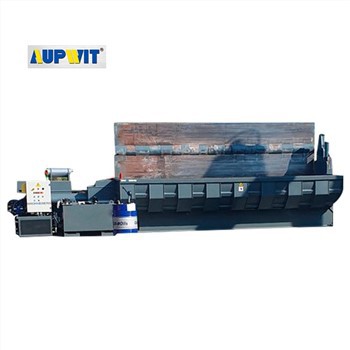
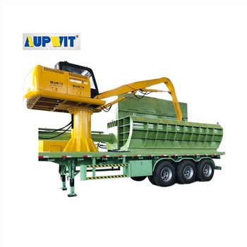
Hydraulic System Operation in Guillotine Shearing Machines
The hydraulic system converts electrical energy into precise mechanical force through a closed-loop mechanism, enabling efficient metal cutting.
Power Generation
Electric motor drives hydraulic pump (gear/vane type) that pressurizes fluid to 140-210 bar:
| Component | Function |
|---|---|
| Electric Motor | Provides rotational energy |
| Hydraulic Pump | Generates system pressure |
| Reservoir | Stores filtered hydraulic fluid |
Pressure Regulation
Valves control and direct fluid flow:
- Pressure relief valve prevents overloads
- Directional valves route fluid to cylinders
- Flow control valves adjust cutting speed
Mechanical Action Components
- Main Cutting Cylinder: Double-acting cylinder drives blade downward (140-210 bar)
- Return Mechanism: Counterbalance valve controls ascent
- Auxiliary Cylinders: Adjust backgauge and blade gap
- Clamping Cylinder: Secures material before cutting
Fluid Management
Closed-loop system maintains fluid quality:
- Reservoir with filtration system
- Heat exchangers (air/water-cooled)
- Suction and return lines
- Contamination monitoring
Safety Systems
Critical protection mechanisms:
- Proximity switches for position control
- Pressure sensors for real-time monitoring
- Emergency stop valves
- Overload protection circuits
Typical Cutting Cycle
- Operator sets parameters (backgauge, blade gap)
- Start button activates clamping cylinder
- Directional valve shifts to extend cutting cylinder
- Blade descends at controlled speed (flow control valve)
- Proximity switch detects cut completion
- Valve reverses to retract blade and release clamp
- System resets for next operation
This precisely controlled hydraulic system enables guillotine shearing machines to deliver consistent, powerful cutting performance while maintaining safety and operational reliability across industrial metalworking applications.


